

(1).Overview
(2).Introduction to Product Features
(1).Installation and Operation Requirements
(3).System Operation
(1).Lens Structure
(2).Lens Maintenance
Before using the handheld laser cleaning machine, users must read this instruction manual carefully.
If you encounter intractable problems during use, please contact us in a timely manner, and we will give you a satisfactory reply as soon as possible.
When unpacking, please check the user manual in the accessory box. If the manual is incomplete, please contact our company promptly.
The handheld cleaning machine produced by our company adopts a subversive model: integrated host and wire feeder. It is an integrated equipment integrating wire feeder, laser and control system, featuring small size, long service life and easy mobility. The optical cable connecting the cleaning head and the machine is about 10 meters long, allowing cleaning work to be carried out in a larger area without moving the machine. In addition, the laser has good beam quality, fast cleaning speed, firm and beautiful welds, bringing users a better laser cleaning solution.
The handheld cleaning machine is equipped with an intelligent cleaning head, which can flexibly cope with various objects and angles. The adopted main intelligent control system has an attractive interface and is easy to operate, allowing users to set different cleaning power, cleaning parameters and alarm information on the operation panel respectively.
The cooling system adopts air-cooled mode, with stable and reliable performance, low failure rate, high efficiency and energy saving.
The whole machine is lightweight and portable, meeting the needs of mobile cleaning.
The handheld cleaning machine is mainly designed for laser cleaning of long-distance and large workpieces, overcoming the limitations of the worktable stroke space. It has a small heat-affected zone during cleaning, which will not cause workpiece deformation, blackening or traces on the back. Moreover, it has a large cleaning depth and achieves thorough cleaning.
It is widely used in aerospace, shipbuilding, instrumentation, machinery, electronic products, automobile, kitchenware and other industries.
It also applies to automobile and parts industry, motorcycle and parts industry, agricultural machinery industry, engineering machinery industry, construction machinery industry, two and three wheel vehicle industry, fitness equipment industry, pressure vessel industry, new energy vehicle industry, hardware industry, etc. It can also be used for precision cleaning of metal materials, especially in the 3C industry.
--1. Strong ability of customized machine development, able to create exclusive models according to customer requirements.
--2. Support for multiple languages
--3. 24-hour constant temperature control
--4. Complete cleaning process library
--1. Can be integrated into automated production lines to achieve batch operation.
--2. Can be equipped with a manual rocker arm.
--3. Cooperate with industrial robots or mechanical arms for external light output control to realize the construction of standardized factories.
--4. Intelligently expand more functions to realize more combined welding and cutting integration.
Standard Voltage:
Laser power: Pulsed 300W; Rated voltage: 220V 50/60HZ;
Electrical requirements: Prepare a (32A) circuit breaker;
Environmental requirements: Good ventilation, no flammable and explosive items around the machine working area.
Total machine power: The total power of the air-cooled handheld cleaning machine is 1.5KW;
The control unit and control panel should avoid electromagnetic wave interference;
To prevent fire, appropriate fire extinguishers should be equipped, and fire exits should be reserved on site.
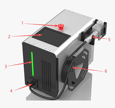
1. Emergency stop button 2. Operation panel 3. Three-color indicator light 4. Optical cable light output port 5. Cleaning head 6. Wire reel
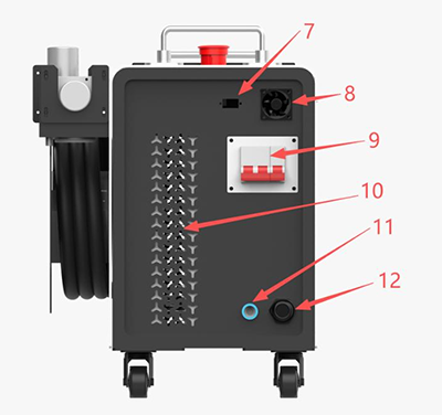
7. 232 interface 8. Heat dissipation fan 9. Main power switch 10. Heat dissipation grid 11. Air pipe interface (not required for some cleaning machines) 12. Main power cord inlet
Note: The machine needs to be connected to AC220V alternating current, rated voltage: 220V 50/60HZ;
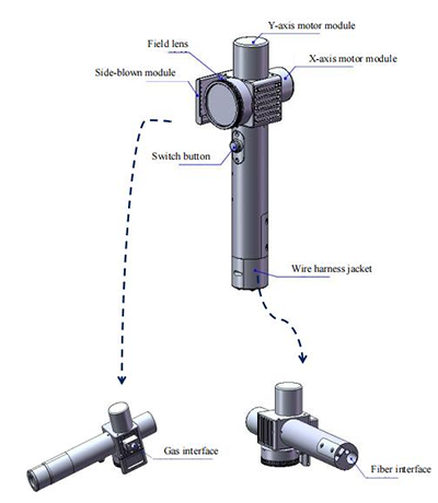
Y-axis motor module
Field lens
X-axis motor module
Side-blown module
Switch button
Wire harness jacket
Gas interface (side blowing)
Fiber interface
Shielding gas interface
Shielding gas connection and usage requirements:
Note: Commonly used gases: Compressed air (oil-water filtration required)
Commonly used gases include: Argon, Nitrogen, Compressed air (oil-water filtration required).
Connect a 6mm air pipe, whose main function is to cool and take away excess heat through internal structural parts when the optical path in the cavity generates heat, so as to ensure cleaning performance.
Before use, ensure that all electrical connections (including protective gas and ground wire connection) are completed.
If conditions permit, all connectors must be tightened and fixed with screws.
Do not directly look at the laser output port when operating the laser. Be sure to wear safety goggles, sound insulation earplugs and masks strictly before operation.
Please turn off all power switches of the laser before wiring operation.
Connect the power cord of the handheld cleaning machine to the prepared air switch according to the marks on the reserved wires, and connect the power plug of the air pump to the power strip. Ensure that all circuit connections are correct to prevent damage to electrical components and unnecessary losses after power-on.
(1) Connect the power input to the specified voltage, phase and frequency;
(2) Connect the safety ground lock to the corresponding interface (this step can be ignored for cleaning machines)
(3) Connect the shielding gas pipe (outer diameter 8mm) to the air pipe interface and open the valve; (this step can be ignored for cleaning machines)
(4) Turn on the power switch at the back of the machine;
(5) Release the emergency stop switch on the front of the machine;
(6) Click the touch screen to enter the software interface and adjust the corresponding parameters (laser power, swing amplitude, swing frequency, blowing on/off delay, power ramp up/down, light output mode, etc.);
(7) Open the gas valve and adjust the shielding gas flow rate to 15-20L/min; (this step can be ignored for cleaning machines)
(8) Clamp the alligator clip on the workpiece to be processed; (this step can be ignored for cleaning machines)
(9) Turn on the laser start option and laser enable option;
(10) Press the cleaning head switch to emit light.
Main Page:
Status Display Area 1: Chiller, Working, Laser, Main Interface, Menu Area
Parameter Area: Laser Power (w), Current Parameter No., Laser Frequency (Hz), Duty Cycle (%), Scanning Speed (mm/s), Scanning Type, Scanning Series, Scanning Length (mm), Phase Increment, Scanning Width (mm), Scanning Density
Operation Status Area 2: Scanning, Blowing, Light Emitting
Status Display Area 1: Chiller、Working、Laser、Menu Area
Current Parameter No.
Laser pulse (W) 1000、Laser frequency (Hz) 5000、System parameter
Parameter Region:Duty ratio (%) 100、Scanning speed (mm/s) 5000、Advanced parameter
Scanning type、Scanning series
Scanning length 10.0、Phase increment 10
Scanning width (mm) 10.0、Scanning density
Operation Status Area 2:Scanning、Blowing、Light Emitting
The menu of the entire system is divided into three parts: [Main Interface], [System Parameters] and [Advanced Parameters]. The main interface can set different scanning and laser-related parameters, and can display system status and alarm status information in real time; the system parameters can set system-related parameters, alarm parameters and authorization management. Advanced parameters can set higher-level restrictive parameters, and a password is required to enter the advanced parameters.
The main interface is divided into four areas: [Status Display Area 1], [Operation Status Area 2], [Parameter Area] and [Menu Area].
[Status Display Area 1]: Used to monitor whether the work lock signal, laser alarm and water chiller alarm are triggered. Normal processing can be carried out only when the display is green.
[Operation Status Area 2]: Used to display the processing status and can also perform manual touch operations. Click
[Parameter Area]: Including scanning parameters and laser parameters
Current Parameter No.: The system supports setting and selecting 9 groups of different parameters. It supports direct selection of current parameters, and also supports parameter number selection in linkage mode with external PLC. For the calling method, refer to the linkage description of system parameters.
Scanning Times: Used to set the number of scans during processing. Select '' to keep scanning when the start button is pressed.
Laser Power: Used to set the peak power of the laser.
Laser Frequency: Used to set the frequency of the laser PWM modulation signal.
Laser Duty Cycle: Used to set the duty cycle of the PWM modulation signal of the continuous laser; continuous laser must be selected in advanced parameters.
Laser Pulse Width: Used to set the pulse width of the pulsed laser; pulsed laser must be selected in advanced parameters.
Scanning Speed: Used to set the scanning speed of the galvanometer.
Scanning Type: Used to set the galvanometer scanning waveform. Supports 11 types of waveforms including '', '', '', ''.
Scanning Length: Used to set the scanning length of the galvanometer.
Scanning Width: Used to set the scanning width of the galvanometer.
| Scanning Width (mm) | Scanning Speed mm/s (Upper Limit) |
| 200-300 | 30000 |
| 50-200 | 20000 |
| 40-49 | 18000 |
| 30-39 | 14000 |
| 20-29 | 12000 |
| 10-19 | 6000 |
| 5-9 | 3000 |
| 3-5 | 2000 |
| 1-3 | 1000 |
Scanning Series: Used to set the number of sine waves during scanning. It is a special parameter for sine wave filling rectangle.
Phase Increment: Used to set the phase change value for each scan. It is a special parameter for sine wave filling rectangle and straight line rotating into circle.
Scanning Density: Used to set the density of each sine wave during scanning. It is a special parameter for sine wave filling rectangle.
Scanning Interval: Used to set the interval between each straight line during scan filling. It is a special parameter for straight line filling rectangle and straight line filling circle.
Filling Type: Used to select unidirectional and bidirectional filling types during scan filling, including '', '', ''. It is a special parameter for straight line filling rectangle and straight line filling circle.
Thread Pitch D: Used to set the pitch between each circle during spiral scanning. It is a special parameter for spiral scanning.
Maximum Diameter D2: Used to set the maximum diameter during spiral scanning. It is a special parameter for spiral scanning.
Minimum Diameter D1: Used to set the minimum diameter during spiral scanning. It is a special parameter for spiral scanning.
Replacement parts are assembled in a dust-free workshop. Except for the first front protective lens which can be disassembled and assembled, disassembly of other modules is prohibited in principle. If it is necessary to check the collimating lens, focusing lens and galvanometer lens, place the product in a clean environment for removal.
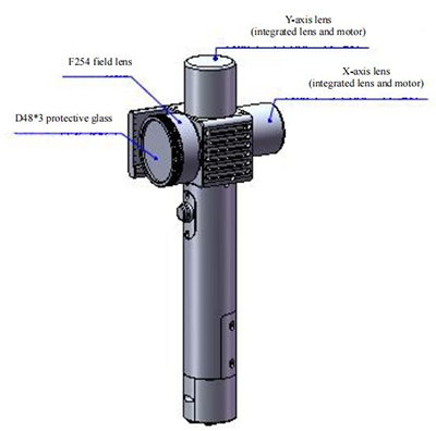
Y-axis lens (integrated lens and motor)
F254 field lens
X-axis lens (integrated lens and motor)
D48*3 protective glass
To clean the cleaning head protective lens window, you need the following equipment:
Cleaning method: Spray isopropanol on a dust-free cleaning cotton swab. Hold the lens facing your eyes, gently pinch the side edge of the lens with your left thumb and index finger, hold the dust-free cleaning cotton swab with your right hand, and gently wipe both sides of the lens in a single direction from bottom to top or left to right (do not wipe back and forth to avoid secondary pollution of the lens). Then blow the lens surface with canned dry and pure compressed air to confirm that there is no foreign matter on the lens surface after cleaning.
Notes:
◎ Before using this product, check the cleanliness and damage degree of the protective lens. Using a dusty or damaged protective lens will damage the cleaning head (focusing lens, extension tube, etc.) and affect the effect.
◎ Private disassembly of the cleaning head and laser product will result in the loss of the warranty right of our company.
◎ Please clean the product in a dust-free environment with powder-free gloves or finger cots. Huanri Laser will not provide warranty for cleaning head damage caused by improper operation or incorrect cleaning procedures.
◎ The concentration of anhydrous ethanol used for cleaning must be greater than 99.5%.
The disassembly and assembly process must be completed in a clean place, and dust-free gloves or dust-free finger cots must be worn when disassembling and assembling the lens.
Disassembly and assembly steps:
Step 1: First clean all dust on the surface of the laser head.
Step 2: Rotate counterclockwise to take out the locking ring, then the protective lens can be replaced.
D48*3 protective glass
Locking ring
Ordinary dry and clean air (air pressure lower than 0.2mpa, avoid directly blowing electrical components) can be used to clean internal dust.


Jinan LaserMen CNC Equipment Co.,Ltd
No.13908, Hehua Road, Licheng District, Jinan City
Shandong Province, China 250100
Tel: +86-531-6781-2013
Mobile, WhatsApp, WeChat, Telegram, BOTIM: +86-15508686690


Copyright © 2019 Jinan LaserMen CNC Equipment Co. Ltd. All Rights Reserved
